Intro
 I own a small telescope - a Celestron firstscope 80mm refractor, purchased many years ago.
It's good for planetary and bright object viewing, and
not so good for any deep space objects, which look exactly like "faint fuzzies". I was interested in astrophotography at the
time so I bought the scope with an equitorial mount so
that it could be used to experiment with astrophotography. However, I did not purchase a motor drive (to drive the RA axis), and soon learned that
this is an almost essential piece of equipment for astrophotograhpy. Instead of buying a motor drive for $90US I resolved to build a
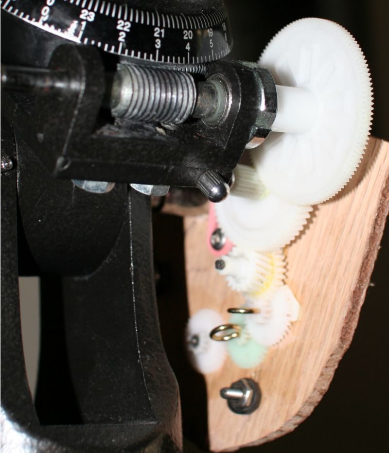
motor drive from scratch using an old stepper motor taken from a floppy drive (as an excercise in electronics!). The
circuit here was built cost about $25, and could be done cheaper.
The design of the drive raised several questions, which I answer on this page; I own a small telescope - a Celestron firstscope 80mm refractor, purchased many years ago.
It's good for planetary and bright object viewing, and
not so good for any deep space objects, which look exactly like "faint fuzzies". I was interested in astrophotography at the
time so I bought the scope with an equitorial mount so
that it could be used to experiment with astrophotography. However, I did not purchase a motor drive (to drive the RA axis), and soon learned that
this is an almost essential piece of equipment for astrophotograhpy. Instead of buying a motor drive for $90US I resolved to build a
motor drive from scratch using an old stepper motor taken from a floppy drive (as an excercise in electronics!). The
circuit here was built cost about $25, and could be done cheaper.
The design of the drive raised several questions, which I answer on this page;
- How can the motor be made to turn at a specific rate?
- How can a stepper motor be driven?
- How does one actually build this?
All of the information used to design and build this driver was gathered from the internet. In particuar three
pages were of great assistance;
Overview
Disclaimer: The circuitry and methods described on this page are for informational purposes only. This circuitry
may not function correctly for your application, or may fail in any application.
The circuit presented here will drive a bipolar stepper motor for use on a telescope. Bipolar stepper
motors have four wires. The circuit can be broken down into four main components;
Schematics: Power - Clock - Control - Drive
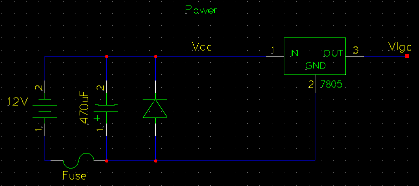
- Power: Simple power conditioning and fusing
- Clock: Adjustable speed for the stepper motor
- Control: Generates a half-stepping sequence to enegerize the coils of the stepper
- Drive: Turns the control signals into high-power to drive the motor coils
Briefly, the circuit works as follows; the clock signal drives 4 D-flipflops in the control section which store the on/off
state of each of the current directions for the two stepper motor coils. The flipflops comprise a FSM
(finite state machine) which advances to the next step of a half-stepping sequence on each rising clock
edge. The drive section provides the current-driving capabilities to turn the control signals into coil-driving
currents. The drive section also includes protection diodes to prevent back-EMF from the motor coils from destroying
the NTE1749/L293 IC.
This circuit is designed to power a 12V stepper motor, and use 5V for logic. If your stepper is not 12V capable the circuit
will require modification. The circuit can be powered with a standard 12V lead-acid battery.
How can the motor be made to turn at a specific rate?
Stepper motor speed is controled by how fast the current direction is switched through the coils (hmm, current direction
switched, sound familiar? like AC power?). The first step in controlling stepper speed is to generate a clock signal
to run the d-flipflops in the control section. The frequency of this clock signal controls how fast the motor steps.
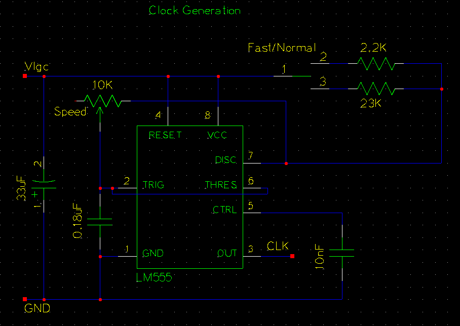
The clock generation circuit shows one way of generating a square-wave signal (clock)
at a specific freqeuncy. There are many good sites which describe the operation of the 555 timer IC used in this circuit,
such as this one at the university of Guelph. The
frequency of the square wave produced by the 555 is controled by the 0.18uF capacitor and the 10k pot / 23k resistors. Timing
is generated from the charging and discharging of the capacitor through the resistors. The switch between 2.2k and 23k for
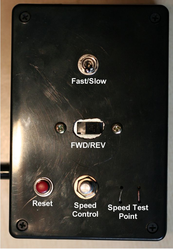
R1 selects track (noraml) or slew (fast) modes. The 10k pot allows fine adjustment of the exact tracking speed. The 10nF
capacitor attached to the reset pin is very important for noisy envrionments - it prevents false resets.
For your setup you may need to modify the resistor or capacitor values to meet your required RPM. The above setup runs at
about 200 half-steps per second, or about 30RPM. Calculating the frequency according to R1/R2/C can be done
online.
How can a stepper motor be driven?
Stepper motors require a specific coil energization sequence to turn in one direction. An incorrect sequence will result
in the stepper motor vibrating in one place. For examples of an energization seqeuence please refer to the reference sites.
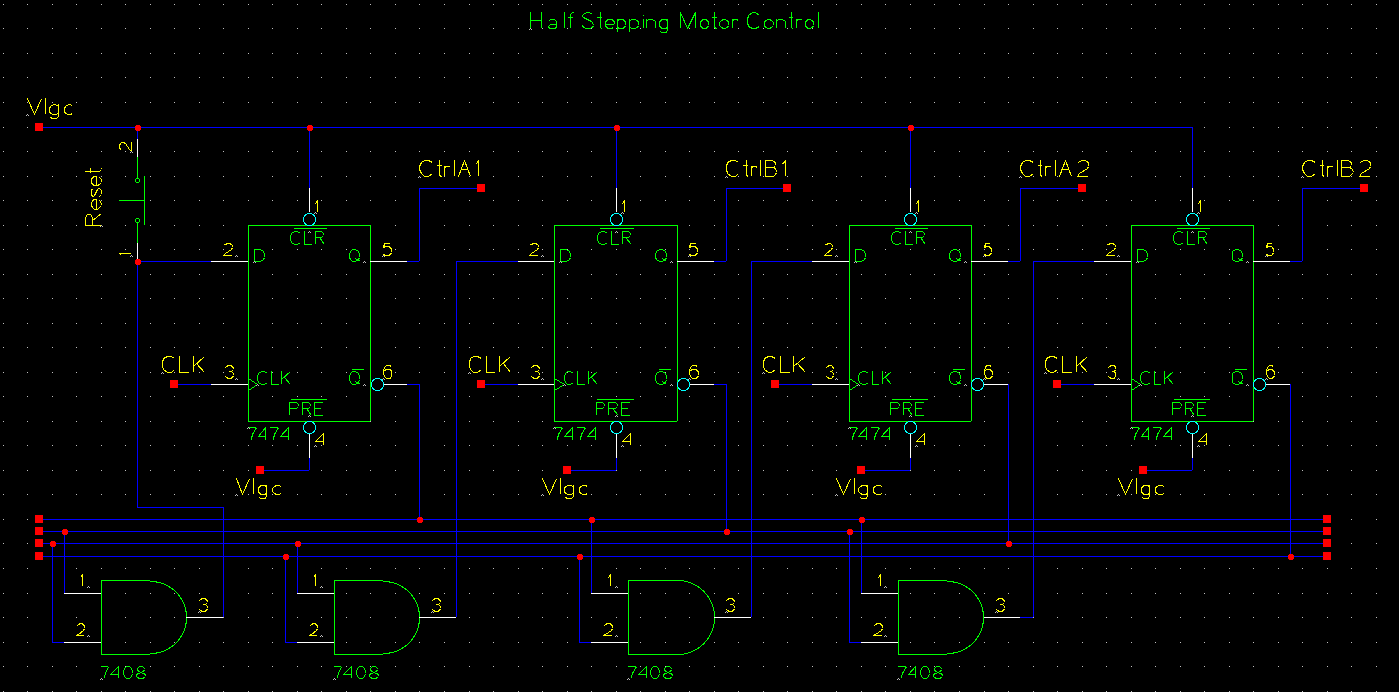
Generating the half-stepping sequence is accomplished with four d-flipflops (on two dual d-ff ICs, 74LS74) and four AND gates (on one
IC, 74LS08). The four flipflops form a state machine that moves through the sequence 1000 -> 1100 -> 0100 -> etc. This
sequence turns the stepper coils on in such a way that the rotor is aligned fully to one coil, then with two
coils on the rotor is halfway to the next step, then fully aligned with the next coil, etc. The Q outputs from the flipflops
form the signals that control current direction and state of the motor coils.
The outputs of the 74LS74 could not provide enough current to power my stepper motor. With a very small motor
it may be possible to use them directly, in which case a power IC is not necessary.
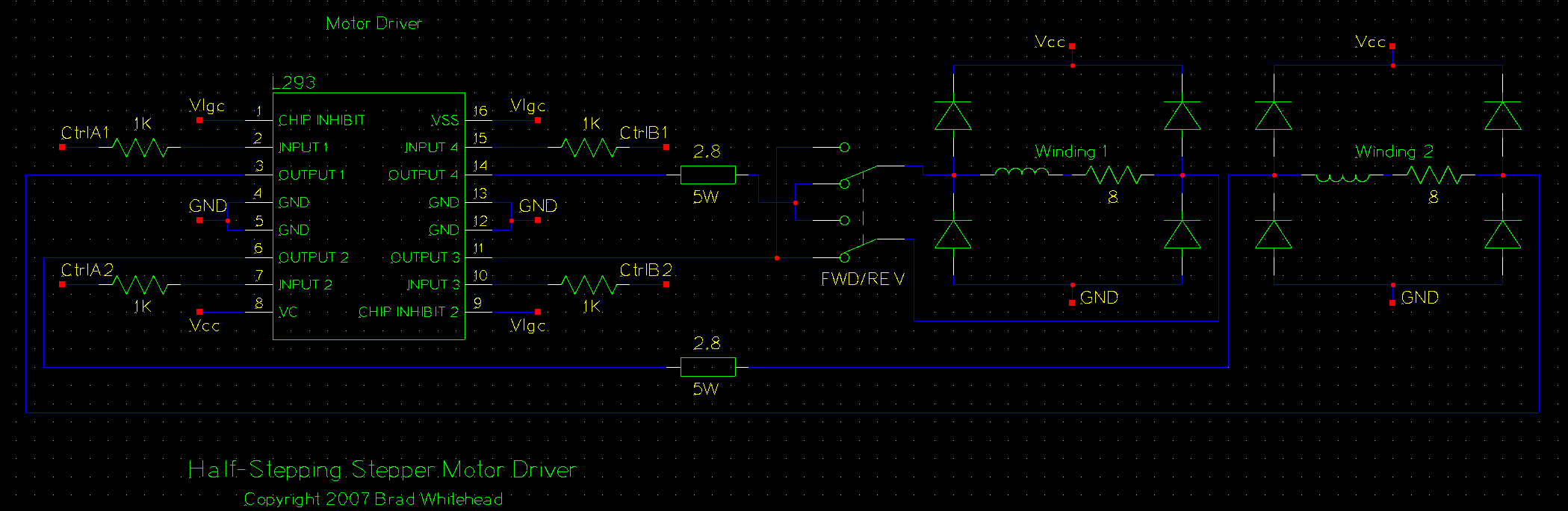
To power my motor, which requires a peak current of about an amp, a dual H-Bidge
IC was used, the L293 (or equivalent, like NTE1749). This IC provides up to two amps peak current. Connection and operation
of this IC is fairly simple, the four control lines are connected to the four chip input lines, and the four outputs
connect to the two motor coils. The chip enable lines are connected to Vlgc. The two "A" lines go to one coil, and the two
"B" lines to the other coil. Use an ohm meter to test the four wires in your motor to figure out the pair for each coil. If
two wires are the same coil the resistance will be around 1-15ohm, otherwise it should be near infinite.
Other circuit notes
Current limiting
Current limiting is an important aspect of stepper drive design. The internal resistance of the motor coils may not be
suffecient to prevent over-current. At slow step-rates the impedance in the coils limits the current for only a relativly
short time, after which the current will be the voltage divided by the internal resistance of the coil. If this current
exceeds the maximum for your motor, your must add some form of current limiting.
The 2.8 Ohm 5 Watt resistors provide resistive current limiting in this circuit. In combination with the 8 Ohm internal
resistance of the coils the power resisitors ensure that the current through the coils will never be more than 1.1 amps.
Protection diodes
The eight diodes on the output stage (four around each coil) are critical for preventing damage from back-EMF. When outputs to
a coil are dropped from 12V to high-impedance the current in the inductor does not stop instantly. If there is no place for the current
to flow when forward voltage is dropped a high voltage spike will occur as electrons "pile up" at the now-"open" switch. The
diodes provide a path for the electrons to flow back through the power supply, thereby preventing damaging back-EMF.
Forward/Reverse
Forward/reverse is easy to add to the circuit by switching the polarity of one of the coils. This is accomplished with a
DPDT (double-pole double-throw) switch.
How does one actually build this?
The circuit can be built in many ways. I would suggest breadboarding the sections first, and maybe even the entire circuit.
I chose a prototype board to build the circuit on. This board has copper contacts on the bottom which the various components
and wires can be soldered to. Total construction time for the electronics was somewhat longer than I was expecting - soldering
took about five or six hours. Everything worked correctly on the first build.
A PCB design would drastically reduce the soldering time. If anyone decides to put one together and is willing to share it,
please let me know and I will post it.
The enclosure box, connectors, and switches were all purchased new, and were the most expensive part of the build.
The finished circuit
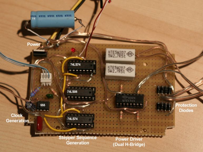
The finished electronics board is shown to the left. The four sections of the circuit are marked out. Power wiring is on
the top of the board, and singals are underneath (not shown). The yellow wires on the top carry the clock singal.
I've been happy with the performance of this drive. Note that it is loud when running due to stepper motor vibration, but
there is no vibration visible at the eyepiece or in photos. A possible improvement would be to convert to a microstepping
design to reduce noise.
|
|

